The process of selecting the XY fraction of the section to sample involves two steps. In this section we will discuss considerations for establishing the parameters of your probe. First, a counting frame size needs to be determined, then the distribution counting frames in our region of interest needs to be established. Finally, we will discuss how to select a height sampling fraction for your tissue sections. The ratio of the counting frame area to the area formed by the distance between counting frames is known as the area sampling fraction, or asf.
SELECTING THE COUNTING FRAME SIZE
To determine the size of the counting frame for use with the Optical Fractionator use a high magnification objective lens with a high numerical aperture (NA) is required. Typically a 60x oil or a 100x oil with 1.4 NA is used. A high NA objective provides a thin depth-of-field. The thinner the depth-of-field, the more accurate is the z position information.
A good choice is to use a counting frame that is large enough to count 1 to 3 cells on average. Make sure that the counting frame is not so large that the edge effect comes into play. More information on the counting frame and the edge effect can be found in the sections on the counting frame.

SELECTING THE SRS GRID OF COUNTING FRAMES
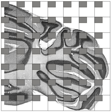
In this study, it was determined that it was appropriate to count aprroximately 600 cell to achieve the desired level of accuracy of the population estimate. See the section on CE and study design for more information. Since 12 sections have been chosen for this study, it will require approximately counting approximately 50 cells per section (12×50 = 600) to achieve this target. Now take into consideration that the counting frame is sized to count an average of 2 cells per counting frame, and will take approximately 25 counting frames per section (2×25 =50). Notice that the sections vary significantly in their profile areas. Section 1, 2, and 12 have relatively small areas compared with the other sections in the series. To take all this into consideration a sampling grid of 300×300 um was selected.
SELECTING THE HEIGHT (thickness) SAMPLING FRACTION OF THE SECTION
The final issue is the size of the guard zones and the Optical Disector height. Typically, guard zones are used to avoid cutting artifacts that occur at the upper and lower surfaces of the sections. Guard zones reduce the available section thickness that can be used for counting. The height of the Optical Disector divided by the mean tissue thickness is the height sampling fraction or hsf.

The figure shows the selected microscopic field at the top surface of the section, at six consecutive focal planes below the top surface with a distance of 3 µm between the focal planes, and at the bottom surface of the section that was found 20 µm below the top surface. Between -3 µm and -18 µm the microscopic field is superimposed by a counting frame; explained in detail in the section Optical Disector. As shown, three nucleoli of Purkinje cells (marked with arrows at -6 µm and -9 µm) fulfilled the counting criteria and were therefore counted. Two other nucleoli of Purkinje cells came into focus at -3 µm and -12 µm, respectively (also marked with arrows), i.e., within the range of the section thickness covered by the height of the Optical Disector. However, both nucleoli were not found entirely within the counting frame or at least hitting one of its inclusion lines and were therefore not counted. Provided the nuclei or the perikarya of the Purkinje cells would have been selected as objects of interest in this example, also, the cells found at -6 µm and -9 µm would have been counted.
PUTTING IT ALL TOGETHER
At this point all of the sampling parameters have been established. None of these settings should be changed while processing this set of slices.
1. Slice interval
2. Counting frame width and height
3. Sampling grid size width and height
4. Optical Disector height
Next, the counting occurs. Here, a computer controlled stereology system would typically be used to count all of the cells from each sampled section that occur in the Optical Disectors. The total population of cells would then be calculated as follows:
Total population = total cells counted x 1/ssf x 1/asf x 1/hsf.
In our example, we wanted to estimate the total number of Purkinje cells in the right cerebellar half of the rat brain shown in Figure 1. To this end, we counted Purkinje cells in the SRS series of sections shown in Figure 1 with Optical Disectors. The base area of the unbiased counting frames (B) was 9,375 µm2 (125 µm x 75 µm), the height of the Optical Disectors (H) was 7 µm, and the top of the Optical Disectors were placed 3 µm below the upper surface of the sections that had an average thickness (t) of 25.3 µm after histological processing. The distance between the counting frames in directions X and Y (D) was 300 µm. This sampling scheme resulted in a total number of 1,670 unbiased virtual counting spaces hitting the cerebellar half, and a number of 898 Purkinje cells that were counted. Accordingly, fractions were calculated as follows:
ssf = 1/5 = 0.2
asf = B/D2 = 9,375 µm2 / (300 µm × 300 µm) = 0.104
hsf = H / t = 7 µm / 25.3 µm =0.277
Accordingly, the estimated total number of Purkinje cells in the right cerebellar half of the rat brain shown in Figure 1 was 155,803.
In summary, the steps for the Optical Fractionator are:
1. Prepare a set of SRS sections.
2. Select a counting frame size.
3. Select a sampling grid size.
4. Select the size of the guard zones and the Disector.
5. Randomly place the sampling grid onto each slide.
6. Use the counting rules at each sampling site to obtain a cell count.
7. Process all of the sections.
9. Calculate the number of cells and the CE.
For more information, see Glaser, J, Green, G, and Hendricks, S. (2007) _Stereology for Biological Research with a Focus on Neuroscience_ (2nd ed.) Williston, VT: MBF Press.,
____________________________________________________________________
![]()
Sponsored by MBF Bioscience
developers of Stereo Investigator, the world’s most cited stereology system